You will need the following tools to successfully complete the replacement of your receipt printer:
- A flat, clean work surface on which to place the APM and components removed during installation.
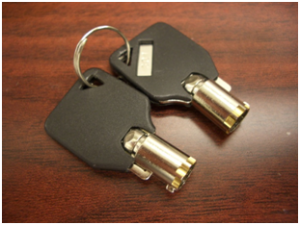
- The keys that are shipped with the APM. (The larger of the two sets, with the number 301 inscribed on it.)
- Phillips Screw Driver (small to medium size)
- The replacement receipt printer
Step 1 – Unlocking Front Bezel |
|
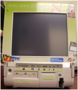
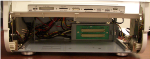
- Place the APM-3700 on a flat surface with the front of the kiosk facing you.
|
|
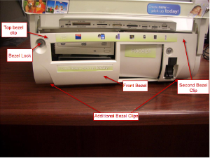
- Insert the larger key of the two sets provided into the lock located on the top, left panel of the kiosk’s front bezel. Set the lock to the “on” position.
|
|
Step 2 – Remove the CD Drive |
|
- .Carefully pry the front bezel cover from the chassis, working from left to right. No tools are required for this step as the design allows for its removal with your bare hands. There are two arrows on the upper left and right corners of the bezel that show where the clips are located. A little pressure should be applied to those locations to free the bezel from the chassis as shown to the right. It may be easier for you to remove the panel if you lay the kiosk on its back, so the monitor is facing up towards you.
|
|
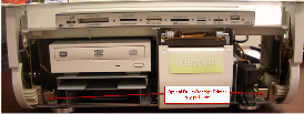
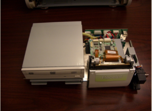
- Completely remove the front bezel and place it somewhere safe. Once the bezel is removed, the Optical Drive and Receipt Printer tray will be exposed.
|
|
- Pull the tray out of the bay using the two silver tabs located near the bottom of the kiosk. A small amount of force needs to be applied to pull the tray out as it is connected to another board in the kiosk.
|
|
Step 3 – Remove/Replace the Receipt Printer |
|
- With the tray out, remove the two ribbon cables that connect the thermal receipt printer (mechanical print head) to the thermal receipt printer’s controller board.
|

|
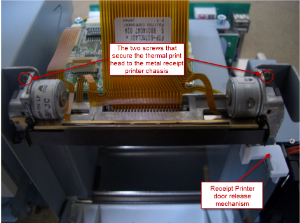
- Once the two ribbon cables are disconnected from the controller board, turn the tray so that the front of the receipt printer is facing you.
- Next, open the receipt printer door. This will give you access to the two small screws that secure the receipt printer to the receipt printer chassis. See pictures on the right panel.
|
|
Step 4 – Remove Rollers from the back of the front panel (only if necessary) |
|
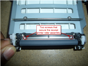
- With the receipt printer door released, use the screwdriver to remove the two screws that secure the roller assembly as shown to the right.
|
|
Step 5 – Remove/Replace the Controller Board (only if necessary) |
|
- There are three screws that secure the controller board to the receipt printer chassis. See images to the right for the location of the three screws to remove.
|

|
Step 6 – Remove/Replace the Power Converter Board (only if necessary) |
|
- The Molex connector that runs from the converter board to the secondary board will need to be removed. First, remove the connector from the secondary board, then remove the connector attached directly to the converter board.
- Next, four screws will need to be removed to replace the converter board. The location of the four screws that secure the converter board in place are marked with circles on the image to the right, and are located on the green circuit board.
|

|